
 sales@dropforging.net
How to Design a Part by Aluminum Forging?
Besides the control of aluminum forging temperature, the design of aluminum forging component is also very important. Parts design mainly includes the standards for machining allowances, parting line location, draft angles, corner and fillet radii for the aluminum forging.
Machining Allowances
Recommended machining allowance for aluminum forging is given in below Table.
|
Greatest
Dimension
(mm)
|
Minimum Finish Stock per
Surface
(mm)
|
|
Less than 200
|
1.6
|
|
200 to 400
|
2.4
|
|
400 to 600
|
3.2
|
|
600 to 900
|
4
|
|
More than 900
|
4.8
|
As shown above, the allowance is referred to as minimum finish stock per surface and is related to the largest dimension of forging. Machining allowance may be applied over the entire forging or to the surfaces to be machined. The finish allowance is applicable to all metals.
Location of Parting Line
Parting line is located along the largest cross-section of the part where the upper and lower dies meet. Thus, parting line is applicable only to forgings produced in closed die forging. Parting line is necessary in closed die forging to remove the finished part easily by separating upper and lower dies.
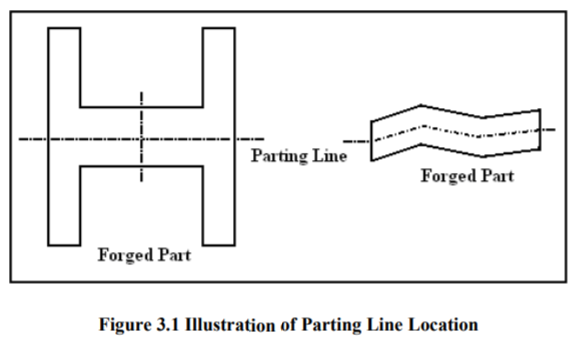
If the parting line remains straight around the periphery of the forging, it will lie in a plane corresponding to that of the mating die surfaces, which is called as the forging plane. Parting line may be in a single plane or it may be curved with respect to the forging plane, depending on the geometry of the final part. Parting line is called as straight parting line if it is on the forging plane and parting line is called as broken parting line if it does not follow the forging plane continuously.
Draft Angle
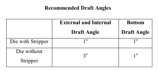
Draft is the angle or taper on the sides of a forging. Draft is necessary for releasing the forging from the dies. Draft can be either applied or natural. Natural draft comes from the part geometry. On the other hand, the applied draft is the taper applied to the walls of a forging to provide sufficient taper to remove the forging easily. If close tolerance forging is made, there is zero or one degree draft is specified in the design of the dies. Thus, strippers or knockout pins are necessary to remove the forging part from the dies in close tolerance forging. The location of maximum draft on any vertical surface usually coincides with the parting line.
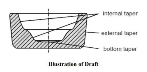
There are basically three types of draft as seen in Figure 3.2. External draft is draft applied to the outer surfaces of perpendicular elements of a forging to the parting line. Internal draft is applied to the inner surfaces of perpendicular elements of a forging to the parting line, including the draft in pockets or cavities. Also bottom draft may exist to provide material flow easily.
Corner and Fillet Radii
Corner and fillet radii are provided to connect smoothly intersecting sides of forging. Corner and fillet help for a smooth, gradual connection rather than sudden angular connection. Corner and fillet radii are usually chosen as large as possible to increase the metal flow and decrease the high forging pressure during forging. If small radius is chosen during design, stress concentration occurs at the small radius and cracks may occur at that point. Choosing of corner and fillet radii also affects grain flow, die wear, the amount of material to be removed in machining. Schematic illustration of the corner and fillet radii is given in below Figure.

Ribs and Webs
A rib is a brace-like projection that is located either at the periphery or on the inside of a forging. Rib can be forged in either the upper or lower die or both. Ribs are called as flange when ribs are along the periphery of a forging. The length of ribs is usually more than three times their width. The design of a rib should reflect the maximum efficiency in use of materials. Efficiency is related to the load carrying capacity of a rib. On the other hand, web is the comparatively thin, plate-like element of the forging. Webs connect ribs and other forged elements. Webs are usually flat and coincide with the forging plane. Because of their physical connection to other elements of a forging, the design of webs should be considered with the design of ribs, the location of parting line, draft and the selection of corner and fillet radii. Due to the material flow in the vertical sides, webs are very difficult to produce.